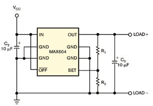
The variable resistor compensates for temperature drift in the regulator if integrated with a programmable temperature index look-up table. In this case, the look-up table can change the resistance every 2 ° C in the range of 40 ° C to + 102 ° C to counteract the temperature-dependent regulator output changes. Typical regulator circuits include a voltage regulator, a feedback resistor divider, and several capacitors that provide filtering and regulation for transient and load switching conditions (Figure 1). The ratio of the two feedback divider resistors sets the regulator output voltage. The regulator generates a preset of 3.3V or any user-defined output within its operating range.

Figure 1, with a typical voltage regulator, you can set the regulated output level by adjusting the R1 / R2 divider.
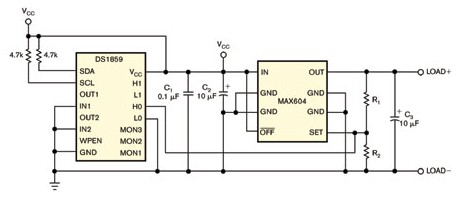
For most regulated circuits, the output voltage will vary slightly with temperature, varying from 97.6% to 101.5% of the nominal voltage of the circuit. These figures are admirable, but you can still improve them further. First, place a digitally controlled variable resistor in the voltage regulator shown in Figure 1 in parallel with R2 (Figure 2). The temperature index look-up table in the internal non-volatile memory controls this 50kΩ digital resistor, allowing you to set different values ​​for each 2 ° C window.

Figure 2 If you connect half of a two-way variable resistor in parallel with R2 to the circuit in Figure 1, you can achieve temperature compensation of the regulated output voltage.
You can set up a look-up table to provide any resistance versus temperature curve. In this example, the look-up table flattens the regulator's normality curve as a function of temperature. Therefore, these lookup tables provide a positive slope for temperature. The resistor has 256 programmable resistance settings, each setting is about 192Ω. In this example, the lookup table is set to 143 (temperature 40 ° C). These settings increase by 1 for each change in temperature from 4 ° C to 6 ° C, so that at ambient temperatures it reaches 152 and 158 ° C at +85 ° C.

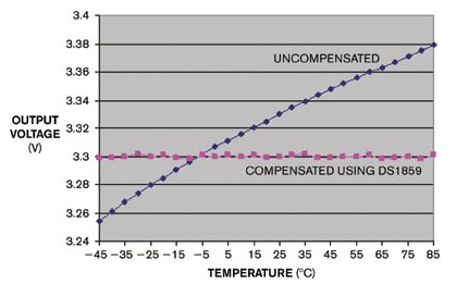
Figure 3 These curves compare the regulated output of the circuit of Figure 1 (black) with the compensated circuit of Figure 2 (pink) versus temperature.
As shown in Figure 3, the voltage regulation performance is significantly improved over the entire temperature range: the variation within 45 ° C to + 85 ° C is now only ± 2mV. For comparison, note the response of the standard regulator circuit in Figure 1 (black curve). The digital resistance IC in Figure 2 contains three ADC inputs for monitoring the external voltage. The DS1847 dual variable resistor offers similar performance as an alternative, eliminating the need for an ADC monitor and lower cost.
123
Graphite Block,Carbon Graphite,Extruded Graphite Block,Applications For Molded Graphite
Henan Carbon Road New Material Technology Co., Ltd , https://www.carbonmoldedgraphite.com
